
Leak Detection and Valve Shutoff Automation with Smart IO Hub


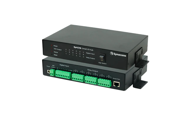
Introducing the SPA-0140 SynLink Smart IO Hub
The SPA-0140 Smart Io Hub is an accessory for SynLink Smart PDUs that provide next-generation automation and environmental sensing solutions. With its advanced digital input sensors ranging from motion detectors to air flow sensors, potential threats are identified and mitigated swiftly.
In addition to sensing, its ability to control a variety of output relay devices, such as actuators and sprinklers, brings a degree of automation that can drastically reduce operational costs. Take, for example, a water leakage in your lab; with SynLink Smart IO Hub solutions, water sensors can detect presence of water and solenoid/ball valves can spring into action to prevent equipment damage, potentially saving thousands in repairs and replacements.
Application: Set up water detection sensors and automate shutoff valves to prevent equipment damage, repairs, and replacements.
Prerequisites
- SynLink Smart PDU
- SPA-0140 Smart IO Hub
- Connected 4 Wire water sensors or 5 wire water sensors
- Compatible solenoid or ball valve 2 wire auto return
- Network Configured/Connected Setup (Quick Start Guide)
- Web Browser with access to SynLink PDU IP Address
Table of Contents
- Connect SPA-0140 Smart IO Hub to your SynLink Smart PDU
- Access SynLink PDU web interface
- Make physical connections for compatible water sensor and automatic valve
- Name your leak detection sensor and solenoid/ball valve
- Create an event action to shut off valve
- Create a trigger to detect leaks with water sensor
- Review all Smart IO Hub triggers and actions
- Shut off all ball valves with front panel user switch for emergencies.
- Set up automatic Email notification for event trigger
1. Connect SPA-0140 Smart IO Hub to your SynLink Smart PDU
Be sure to connect the provided power supply to the Smart IO Hub before connecting sensor ports. Use the provided ethernet cable to connect the Smart IO Hub Sensor Port to your SynLink Smart PDU Sensor Port

2. Access SynLink PDU web interface
Use the Quick Start Guide to setup your SynLink PDU with an IP address.
Navigate to System -> Sensors to show connected sensors and any relevant events/actions.
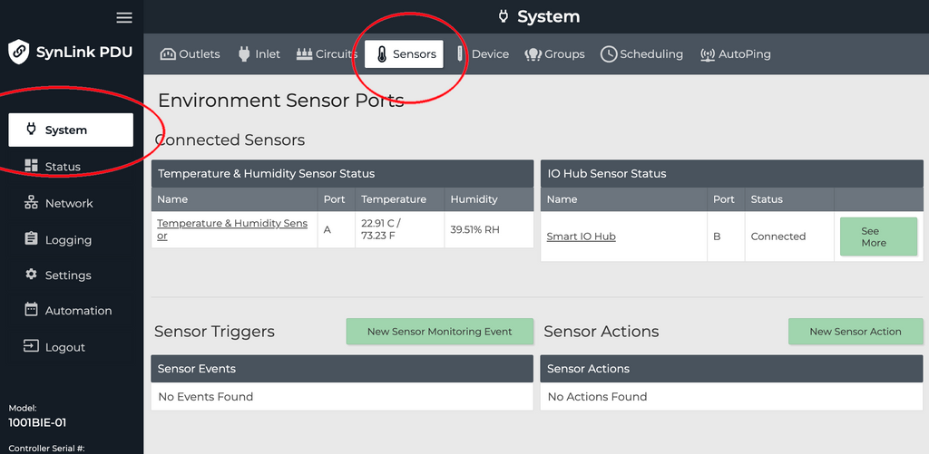
Select "See More" on an IO Hub to navigate to a page to review and modify IO Hub state and settings. In here, you can change Sensor names, Output Relay names, Digital Input names, and OPEN/CLOSE output relays.

3. Make physical connections for compatible water sensor and automatic valve
Water Leak Detection Sensor connection:
 See more details for 4 Wire water sensors or 5 wire water sensors setups.
Electric Ball Valve connection:

See more details for 2 wire auto return connection.
1/2" Brass Electric Ball Valve - 2 Wire Auto Return (9 to 24V AC/DC) used.
4. Name your leak detection sensor and solenoid/ball valve
Naming the leak detection sensor and solenoid ball valve will make managing events, actions, and general usage more intuitive.


5. Create an event action to shut off valve
Event action is an action the PDU takes when triggered by a particular event trigger. We will create an action that will make the attached valve to shut off and stop the flow of liquid.


Select the appropriate Sensor Port, the output relay that is labeled for the attached valve, and the state of OPEN. The example ball valve will cut off the flow of water when provided voltage is cut.
6. Create a trigger to detect leaks with water sensor
Event triggers are always being monitored for conditions that warrant an action. The following trigger will monitor the leak detection sensor and will shut off the valve automatically when triggered.


Be sure to select the Digital Input State High event type. Select the appropriate Sensor Port, the labeled leak detection sensor, and a max time over threshold. With this configuration, if the leak detector is wet, the digital input will change from LOW (dry) to HIGH (wet), and if it stays wet for 5 seconds: the action "Shut off Valve #1" will trigger.
7. Review all Smart IO Hub triggers and actions
On the System -> Sensors page you will be able to see all events and actions you have created. 
History of all event triggers can be found under Logging -> Event Log

8. Shut off all ball valves with front panel user switch for emergencies.
Switch the following user switch to set all output relays to OPEN. In this setup, all attached ball valves will lose voltage, and the valves will shut off. OPEN output relay = CLOSED valve.

9. Set up automatic Email notification for event trigger
See the following guide to set up email notifications for event triggers.
Questions about this set up or any other related setup? Reach out to our electrical team at [email protected].